Perspectives, Slides and Scripts
Introduction
AutoCAD can be used to create a simple "walk through" of any 3D model. For example, if you have designed a new pedestrianisation scheme for a town centre, you could use AutoCAD to give a slide presentation to show how the scheme would look from a pedestrian eye view as the person moved through the space. This is an extremely useful technique for presenting schemes to clients or the general public who may not necessarily have a good understanding of plans.
In order to create such a slide show you need to learn a number of new commands. This handout will describe those commands in the order in which they will normally be used to create a slide show. The commands are: DVIEW which is used to create the perspective views, DDVIEW to save the perspective views, SHADE to shade the views, MSLIDE to make the slides, VSLIDE to view the slides and SCRIPT to run a script file which will automate the process of viewing a number of slides in a predetermined order.
The DVIEW command
| Toolbar | None |
| Pull-down | |
| Keyboard | DVIEW |
The DVIEW command is not an easy command to use, however, it is the only way to create perspective views using AutoCAD. Many third party add-ons for AutoCAD have improved on the DVIEW command, the Perceive command in AEC is a good example. However, the DVIEW command is very flexible and if you learn to use it well you will be able to do much more than is possible with the Perceive command.
Command Sequence
Command:DVIEW
Select objects: (pick a few key objects in the view for visual reference)
Select objects: (pick more or ![]() to end)
to end)
CAmera/TArget/Distance/POints/PAn/Zoom/TWist/CLip/Hide/Off/Undo/<exit>: PO (for the points option)
Enter target point <36.484,25.000,0.000>: .XY (the .XY filter forces AutoCAD to prompt you for a Z value)
of (pick target point)
(need Z): 1.7
Enter camera point <36.484,25.000,0.000>: .XY
of (pick camera point)
(need Z): 1.7 (a viewers eye height is assumed to be 1.7m above ground level)
Camera/Target/Distance/Points/Pan/Zoom/Twist/Clip/Hide/Off/Undo/<exit>: D (for Distance)
New camera/target distance <150.3220>:![]()
CAmera/TArget/Distance/POints/PAn/Zoom/TWist/CLip/Hide/Off/Undo/<exit>:![]()
An Example
Since the DVIEW command is one of the more complicated AutoCAD commands you may find it useful to work through the example below. In order to follow this example you will first need to construct a box and a couple of points as follows:
- Begin a new drawing, select
 from the Standard toolbar or from the pull-down. Select the "Start from Scratch" option.
 - Using the RECTANG
 command, draw a square with corners at 250,150 and 270,170.
 - Start the Properties command, DDCHPROP at the keyboard or select
 from the Object Properties toolbar and give the square a thickness of 15.
 - Change the current point style to something more easily visible. Use the DDPTYPE command, from the pull-down.
- Using the POINT command,
 from the Draw toolbar, draw two points, one at 260,160 (the Target point) and one at 205,135 (the Camera point). You do not need to draw points in order to use the DVIEW command but for the purpose of this example it will help you to visualise what is happening.
 - Now, follow the command sequence, taking care to respond to all command prompts exactly as detailed below.
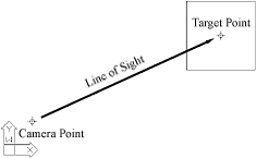 Before starting the DVIEW command, make sure you are in plan view, this makes it easier to correctly locate the Target and Camera points. The AutoCAD drawing area should look something like the illustration on the right.
Command: DVIEW
Select objects: (pick the box and the two points)
Select objects:![]()
The DVIEW command prompts you to select objects because the command works more quickly if it only has to use a few simple objects when it is generating a perspective view. For a relatively small drawing such as the one we're working with at the moment you can select all objects without causing any problems but for large drawings it is advisable to select just a few key objects which you can use as a visual reference while the perspective is constructed. For example, if you wanted a perspective view of a complicated site drawing it would be appropriate to select the site boundary as a reference.
CAmera/TArget/Distance/POints/PAn/Zoom/TWist/CLip/Hide/Off/Undo/<exit>: PO
Although there are a number of ways to construct a perspective view using DVIEW, the Points option is the most appropriate for constructing views when we want to specify particular target and camera points. This is the easiest method to construct a perspective which most closely approximates to a human eye view from a particular point and looking in a particular direction. The Points option prompts us to specify the position of two points, a Target point and a Camera point. The Target point is the point that we want to look at and will appear in the centre of the view. The Camera point is the point from which we look at the Target point. In other words the Camera point is our eye.
Enter target point <36.484,25.000,0.000>: .XY
In order to correctly specify the target point, we need to be able to give AutoCAD a 3D co-ordinate (x,y,z). We can simply enter an xyz co-ordinate at the keyboard if we know the co-ordinates of the point we are interested in. However, in most cases we will need to pick the point in plan. Picking a point in plan gives AutoCAD a 3D co-ordinate but the program assumes that the z value is zero (or whatever elevation is set using Entity Modes). We therefore need to force AutoCAD to prompt us for a z value to add to the xy point which we pick. We can do this by using a "Dot xy filter". Whenever AutoCAD prompts you to pick a point you can use a dot xy filter by typing ".XY" at the prompt.
of (pick xy position of target point)
This is the point you drew at 260,160 using the POINT command. For the purposes of this example just pick a point near the drawn point. If you need to be perfectly accurate when picking a drawn point, you should use the Node Object Snap, ![]() on the Object Snap toolbar.
on the Object Snap toolbar.
(need Z): 10 (enter the z value of the target point, in this case 10m)
Enter camera point <36.484,25.000,0.000>: .XY
The same argument applies to the selection of the camera point as to the target point, so we again must use the dot xy filter.
of (pick camera point)
This is the point you drew at 205,135 using the POINT command.
(need Z): 1.7
By convention it is accepted that adult human eye height is at 1.7m above ground level. Providing that the base plane of our drawing is at zero elevation the z value of the eye height will be 1.7 (if we are working in metres). If the base plane is not at zero then the eye height will be 1.7 plus the base plane elevation. This convention assumes that the viewer is standing on the base plane. If the viewer is sitting, standing on a raised platform, or viewing from the upper storey of a building, the elevation of the Camera point must be adjusted accordingly.
When specifying the z values of the Target and Camera points it is worth considering the effect upon the line of sight. If the Target point elevation is higher than the Camera elevation, the line of sight will be inclined upwards, giving the effect of a viewer looking up towards some elevated point. If the Target point is lower, the line of sight will be inclined downwards. To construct a perspective along a horizontal line of sight, the elevations of Target and Camera points must be the same.
Camera/Target/Distance/Points/Pan/Zoom/Twist/Clip/Hide/Off/Undo/<exit>: D
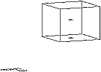 When we have specified the Target and Camera points the DVIEW command displays an axonometric view from the Camera point (see illustration, right) and returns to the main options prompt. To turn this axonometric view into a perspective we must use the Distance option.
New camera/target distance <60.98>:![]()
The distance prompt requests a target distance and gives a default value. The default value is the calculated distance between the Target and Camera points which have just been specified. It is, therefore, the value which should be used. Hit the![]() key on the keyboard to accept the default value.
key on the keyboard to accept the default value.
CAmera/TArget/Distance/POints/PAn/Zoom/TWist/CLip/Hide/Off/Undo/<exit>:![]()
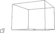 The DVIEW command now displays a perspective view from the Camera point (see illustration, right) and the UCS icon changes to the box symbol to inform you that you are in perspective mode. At the moment you will only see the objects you initially selected in perspective. To complete the DVIEW sequence, hit
 ![]() to exit from the DVIEW command and the whole drawing will be regenerated in perspective.
to exit from the DVIEW command and the whole drawing will be regenerated in perspective.
When in perspective mode there are a number of restrictions which apply. You cannot pick objects and you cannot use the ZOOM command (changes to the view can only be made with the DVIEW command). It is not really feasible to work in perspective mode. To return to normal viewing at any time, use the PLAN command. This will take you from any perspective view back to a plan view of your drawing.
As you can see by the number of options available, there are many ways to create a perspective using DVIEW. This handout concentrates on the most straightforward option for creating perspectives quickly. Many of the other options are very useful and can be used to create interesting effects like wide-angle and telephoto lens simulation (the Zoom option). You may find it useful to experiment with the other options and to refer to the AutoCAD Reference Manual for more information on their use.
Constructing perspective views with the DVIEW command can be quite a tricky process but fortunately there is a way to save any view of your drawing so that it can easily be restored without going through DVIEW again.
Saving perspective views, the DDVIEW command
| Toolbar | |
| Pull-down | |
| Keyboard | DDVIEW |
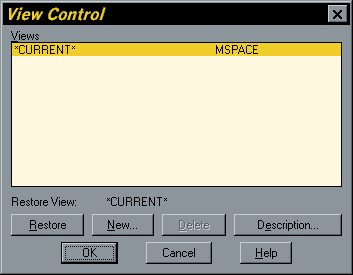 This command can be used to save any view of a drawing, plan, elevation, axonometric or perspective and can also be used to restore these views at any time with just a few mouse clicks.
As you can probably guess by the name, the DDVIEW command is dialogue box driven. The "View Control" dialogue box is shown on the right.
The DDVIEW command saves the current view, so if you want to save a perspective view (or any other view), it must be shown in the AutoCAD drawing area when you start the DDVIEW command.
Saving a New View
To save the current view, start the DDVIEW command and click on the "New…" button which is located near the bottom of the dialogue box.
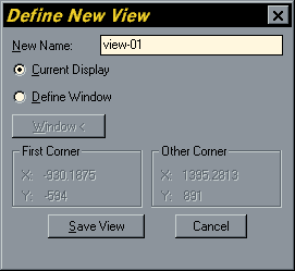 On clicking the "New…" button you are presented with the "Define New View" dialogue box (shown, left). To save the current view, enter a view name in the "New Name" edit box at the top of the dialogue box and click on the "Save View" button.
In common with filenames and names of other AutoCAD properties, view names cannot contain most of the special characters, including: a space, period, asterisk, question mark, brackets, ampersand (&), the "at" symbol (@) or the pound sign. However, as with layer names, you may use hyphens and underscores. If you use an illegal character as part of a view name you will get the error message "Invalid view name" at the bottom of the "Define New Name" dialogue box.
You can save as many views as you like, so it is a good idea to save all the views you need to complete a walk through sequence so that you have easy access to all of the views you need. View names appear in alphabetical order in the "View Control" dialogue box, so if you are saving views which should be viewed in a particular order, you should give them names that will appear in the correct order in an alphabetical list. For example, if you decide to call your views "View-number" and there will be ten or more of them, the first view should be called "View-01", the next "View-02" etc. The reason for this is that alphabetically "View-1" is followed by "View-10" and not "View-2".
Restoring a Saved View
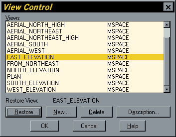 To restore a saved view, start the DDVIEW command again and highlight the name of the view you wish to restore in the view name list (see illustration, right). Click on the "Restore" button, the text above the "Restore button will change to reflect the view you have selected. When you click on the "OK" button the view you have selected will be restored as the current view.
The DDVIEW command saves only the geometry of the view as constructed with the DVIEW command. If you have made changes to your drawing since you saved the view, the restored view will show those changes. It is possible, therefore, to create and save all of your views before completing the drawing. This can be quite effective if you need to return to a view repeatedly in order to consider the implications of design changes.
Deleting a Saved View
 To delete a saved view, highlight the view name in the "View Control" dialogue box and click on the "Delete button. The view name will be removed from the list.
Displaying the View Description
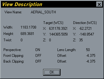
To display the "View Description" dialogue box, highlight a view name in the "View Control" dialogue box and then click on the "Description…" button. The "View Description" dialogue box is illustrated on the right.
Shading the view, the SHADE command

| Toolbar | |
| Pull-down | |
| Keyboard | SHADE |
The SHADE command can be used to give a 3D perspective view a solid look. It works by shading every 3D face with a solid colour.
 The illustration on the right shows a view of a cylinder as it would look in an AutoCAD drawing. The cylinder on the left has been shaded using the SHADE command. Notice that all hidden lines are obscured by the shaded faces, giving a solid effect.
When you have shaded a view, you cannot pick drawing entities, nor can you use the ZOOM command. A shaded view is just like a photograph of the original drawing, it cannot be modified. To return to normal viewing mode you must use the REGEN command to regenerate the drawing. The shaded view will then disappear and you can continue as normal.
The SHADEDGE variable
 You can change the shaded effect that the Shade command gives to your drawing using the SHADEDGE variable. To change the SHADEDGE variable just enter "SHADEDGE" at the keyboard and enter a value between 0 and 3. The default value for SHADEDGE is 3. The shaded cylinder above was shaded with SHADEDGE set to 3. You can also use the SHADE command with preset SHADEDGE values from the View pull-down (View/Shade/options). The following list describes how each SHADEDGE value affects the shaded image and indicates the corresponding option from the pull-down.
SHADEDGE = 0 gives a shaded colour surface with no lines, "256 Color" (below left).
SHADEDGE = 1 gives a shaded colour surface with lines, "256 Color Edge Highlight". This tends to give the best overall results (below centre).
SHADEDGE = 2 gives a background colour surface which creates a similar effect to the HIDE command, "16 Color Hidden Line" (below right).
SHADEDGE = 3 gives a block colour surface, "16 Color Filled", this is the AutoCAD default.
 |
 |
 |
Slides
AutoCAD Slide files contain snapshots of the AutoCAD drawing area. An AutoCAD slide is a file with a ".SLD" extension. For example, if you create a number of slides which are to appear in sequence, the first one might be called "VIEW-01.SLD". You can save any view of a drawing as a slide, but slides are particularly useful for saving shaded images.
Making slides, the MSLIDE command
| Toolbar | none |
| Pull-down | none |
| Keyboard | MSLIDE |
The MSLIDE command can be used to save any view of a drawing to a file.
When you start the MSLIDE command you are presented with the familiar file dialogue box. The main difference between the "Create Slide File" dialogue box and the "Save Drawing As" dialogue box is that the file pattern has been changed from "*.DWG" to "*.SLD". This means that you will be creating a slide file and not a drawing file. To create a slide file, enter the slide name in the file edit box and click on the "OK" button. Remember, you cannot use any of the special characters (see above).
Viewing slide files, the VSLIDE command
| Toolbar | none |
| Pull-down | none |
| Keyboard | VSLIDE |
The VSLIDE command can be used to view any slide file created with the MSLIDE command.
The VSLIDE command also uses the familiar file dialogue box. To view a slide, highlight the file you wish to view and click the "OK" button. The slide is displayed on the monitor screen in the AutoCAD drawing area. The slide is just a two dimensional image, like a photograph, and cannot be modified in any way. To return to your drawing, use the REDRAW command, the slide will disappear and the normal drawing view will be displayed.
Script Files
Script files can be used to automate any AutoCAD command sequence. Scripts are text files which list a sequence of AutoCAD commands, one on each line. When the script is run, AutoCAD executes each command just as if you typed them from the keyboard. Scripts provide an ideal method for automating the process of displaying a number of slide files in a predetermined sequence.
![]() To create a script file you need to use a text editor such as Notepad. It doesn't matter which text editor you use provided that the file format is plain ASCII text and that the saved file has a ".SCR" extension. To start Notepad, click on the "Start" button at the bottom left of your screen, select "Programs" then "Accessories" and click on the Notepad icon.
To create a script file you need to use a text editor such as Notepad. It doesn't matter which text editor you use provided that the file format is plain ASCII text and that the saved file has a ".SCR" extension. To start Notepad, click on the "Start" button at the bottom left of your screen, select "Programs" then "Accessories" and click on the Notepad icon.
Below is an example of a script file which displays three slides, one after the other and then returns to the normal drawing view by issuing the REDRAW command:
VSLIDE VIEW-01
VSLIDE VIEW-02
VSLIDE VIEW-03
REDRAW
As you can see, each command is on a new line and the command parameter, in this case the slide file name, is separated from the command string by a single space. There is no need to add the ".SLD" extension since the VSLIDE command assumes that you will want to view a slide file.
The DELAY command
If you ran the script above just as it is shown, each slide would be displayed on the screen and then immediately replaced with the next slide. This doesn't give enough time for us to view the slide properly. We need some method of pausing before moving on to the next slide. The DELAY command can be used to insert a pause between each VSLIDE command. If we add DELAY to the script above, the script file would look like the one below:
VSLIDE VIEW-01
DELAY 6000
VSLIDE VIEW-02
DELAY 6000
VSLIDE VIEW-03
DELAY 6000
REDRAW
The syntax for the DELAY command is:
DELAY Time in milliseconds
There are 1000 milliseconds in a second, so there is a pause of 6 seconds between each slide in the script above. You can use any number between 1 and 32767 with the DELAY command. This means that you can pause between any two commands from one millisecond to just under 33 seconds. Of course, if you need to pause for more than 33 seconds, you could use two DELAY commands, one after the other.
The RSCRIPT command
The script above displays each slide, pauses for 6 seconds, views the next slide and then uses the REDRAW command to return to normal viewing. However, sometimes we may want to have the script loop, so that when it gets to the end of the script it will start again at the top. We can do this using the RSCRIPT command and create a rolling slide show which will continue to repeat itself until we stop it. To change the script above into a loop, just replace the REDRAW command with the RSCRIPT command.
The final script would look like the one below:
VSLIDE VIEW-01
DELAY 6000
VSLIDE VIEW-02
DELAY 6000
VSLIDE VIEW-03
DELAY 6000
RSCRIPT
You must always end a script file with a carriage return, otherwise the script will pause indefinitely and the last command will never be issued. In the above example a carriage return must be added after the "T" of "RSCRIPT". This is a common mistake and is difficult to spot because the script file doesn't look any different.
The RESUME command
You can suspend the operation of a script at any time by hitting the Backspace key. You may, for example want to pause a little longer at a particular slide in order to talk about it if you are giving a presentation. Once the Backspace key is pressed the script stops. To continue the script where you left off, use the RESUME command. Just type "RESUME" at the command prompt and the script will restart from the point at which Backspace was pressed.
Running a script file, the SCRIPT command
| Toolbar | none |
| Pull-down | |
| Keyboard | SCRIPT |
The SCRIPT command is used to start the operation of a script file.
The SCRIPT command uses the familiar file dialogue box, but only displays ".SCR" files. To start running a script, highlight the script file you want and then click the "OK" button at the bottom of the "Select Script File" dialogue box.
Creating a "Walk Through"
We have now covered all the commands required to put together a walk through. To recap, the steps to creating a simple walk through are set out below:
- Create a 3D drawing of your design scheme.
- Decide on the position of the Camera and Target points and use DVIEW to construct a perspective view.
- Save the perspective view as a "Named View" using the DDVIEW command.
- Shade the perspective view using the SHADE command, consider the different SHADEDGE options.
- Create a slide file from the shaded view using the MSLIDE command.
- Repeat steps 2-5 for each view you want to use as part of the walk through.
- Use a text editor to write a script file which will display your slides.
- Run the script file using the SCRIPT command.
This tutorial has concentrated on creating slide shows which are composed of perspective views but you could use slides to display any view of an AutoCAD drawing. For example, you may want to start a presentation with a logo or some introductory text. You may also want to add annotation or a title slide between each view. You can even create slides from Paperspace, so you could add annotation to your perspective views, or any other view. Be creative in your use of slides and scripts and consider using script files for other purposes.
Donate to CADTutor
If you found this tutorial useful, you might like to consider making a donation. All content on this site is provided free of charge and we hope to keep it that way. However, running a site like CADTutor does cost money and you can help to improve the service and to guarantee its future by donating a small amount. We guess that you probably wouldn't miss $5.00 but it would make all the difference to us.
Local Navigation
Sponsored Links
The Basics
- Dual Dimensions in a Dim…
- UCSICON Options
- "Best of" Basics: Irreg…
- Tool Palette Basics
- Original Dimension Value
- Possible Solutions to th…
- Avoid Using 'Standard' i…
- Shorten the Plot Scales…
- Update the Source File B…
- User Increment Angles fo…
- Drawing Information
- 'Sign Language'
- Rotate with the Copy Opt…
- Use the INSERT Osnap on…
- To or From the Current L…


