 Michael’s Corner #47
November 2006
A2007 Visual Styles & Text Stuff
That's a rather odd combination of topics, admittedly, but I think you'll find them worth the browse. With much ado, AutoCAD 2007 was heralded as having all these wonderful new 3D abilities. It is, in fact, quite exciting, however all of the 3D-related features are not necessarily "New". There has always been the ability to apply materials, position lights, generate 3D solids and run the Boolean routines of Union, Intersect, and Subtract. In this month's main article I just wanted to quickly pique your interest and show you the Visual Styles you can use to view your 3D objects in AutoCAD 2007. If you want me to send you the drawings shown in this article, email me at michael.beall@autocadtrainerguy.com and I'll send them your way.
As I was working with A2007's Mtext the other day, I was quite pleased to see the Line Spacing option, so I wanted to bring that to your attention. Then when I was working in a drawing someone sent me, I was unable to edit the height of the dimension text and I knew at that point that the text Height had been preset in the Text Style. This is something that I will occasionally get emails regarding, so I wanted to illustrate why a preset text Height is not always a recommended approach when creating the text style.
Finally, I was surprised to see that I hadn't covered the Distance command in the Basics section over the last nearly four years (!), so in a rather uncharacteristic manner, I used an engineering drawing to illustrate this powerful feature. Now I have an article to reference when I'm on the road and people ask me how to find distances!
If you would like to contact me directly, you can do that also.
Blessings to one and all,
Michael
A2007 3D Visual Styles
 There are two ways to access the Visual Style options. One way is from the shortcut menu of the Constrained or Free Orbit commands, the other is from the Dashboard []. My thought is that you will find the Dashboard much more exciting simply because of the additional features it offers.
Note: Obviously, to take advantage of the 3D visual styles, you'll have to have a 3D object. In my February 2006 column I introduce 3D Orbit and step you through how to make a quick 3D object. Also, you may want to consider saving your current view [] so you can return to it later after playing in this 3D sandbox.
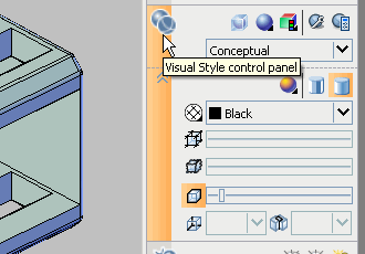
Visual Style Control Features
There are lots of really wonderful things on the Dashboard, and this is not an exhaustive (exhausting??) review, but here are a few you may want to play with…
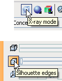
- Expand the Visual Style Control Panel to display all of the available features.
- Take a look at X-Ray Mode in the upper pane of that panel; pretty cool!
- Curiously, before you can use the slide bars for the features in the lower section, you have to click the feature button first to turn it on, then you have access to the slider.
Personally, I think the sliders are a bit wimpy, but you get used to it. Regardless, all of those features are pretty fun to play with. Next issue I'll cover saving a Visual Style.
Power Tool
Mtext Line Spacing
This one may have slipped past me (OK, it probably did) but it's worth mentioning, nonetheless. Prior to my system crash a few weeks ago, I had A2005, A2006, & A2007 loaded and could have checked other versions. As it stands, I know for sure that AutoCAD 2007 has this Line Spacing feature in Mtext that formerly could only be adjusted in the Properties window*.
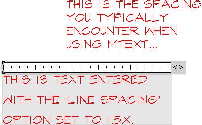
Instructions to set a Line Space Factor when Adding Mtext
- Launch Mtext and pick the first corner.
- Enter L for the "Line spacing" option. You can either use the At least option or the Exactly option. In this situation, I used A for At least.
- When entering the spacing factor, be sure to add the X at the end. I couldn't figure out why it "wasn't working" and then realized it needed that X.
- Now when you enter the text, when it wraps you will see the spacing difference. In the illustration the upper text was entered using the default spacing of 1x.

* If you have a version of AutoCAD that does not have this "Line spacing" option, to adjust the line spacing of existing Mtext, select the text object, then open the Properties window. Under the Text heading, you will see the three Line Space settings as shown. (If you're thinking "Oh, I remember that", you probably saw it in the Odd Spot coverage back in Michael's Corner, July 2004.)
The Odd Spot
Dimension Text Height
Have you ever been unable to adjust the text height of a Dimension?
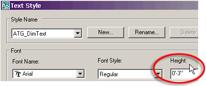
Culprit: The Height of the dimension's Text Style is preset. Very aggravating. In the figure, you see that the text height is set to 6″ in the Properties dialog box, but the preset Height of 3″ supersedes that value.
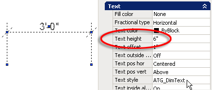
Solution: Using Properties, identify the name of the Text Style for that dimension, then in the Text Style dialog box, set the Height to 0″. When you Apply and Close the Text Style dialog box, the dimension text will update as necessary.

The Basics
The DISTANCE Command
There is more to the Distance command than meets the eye. Literally. If you have adjusted the height of your Command line bar to be less than three lines high, you aren't getting the full report when you use the command.

If you expand the height of the Command line bar (or hit F2 for the AutoCAD Text Window), you will see there is quite a bit of information that is returned from the two points you pick.
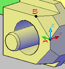
For reference purposes, I set the UCS onto the front corner of this part, then used the Distance command with Endpoint snap and picked point A, then point B. The X-Axis is red, the Y-Axis is green and the Z-Axis is blue.
Here's what you get from those two picks
Distance = 0.233 Physical distance between point A & B.
Angle in XY Plane = 90 Emphasis on "in". Looking down on the XY plane, the angle of an imaginary line from point A to point B; calculated counterclockwise from 0 (the X-Axis).
Angle from XY Plane = 45 Emphasis on "from". Put a pencil on the table (the XY plane), tilt one end up and the pencil is identifying and angle "from" the XY plane.
Delta X = 0.000 Not a sorority; "Delta" means "change in". Since every point in AutoCAD has an X,Y,Z coordinate, a Delta X value means there was no change in the value of the X-coordinate for points A and B.
Delta Y = 0.165 The difference between the Y-coordinates for those two points was 0.165.
Delta Z = 0.165 Ditto for the Z-coordinates.
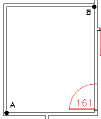
For 2D drawings, use the Distance command one time to find the size of a room by picking points between the diagonal corners…
Distance = 16′5-7/16″, Angle in XY Plane = 50.34,
Angle from XY Plane = 0.00, Delta X = 10'6″,
Delta Y = 12′8″, Delta Z = 0′0″
Left Field
Flash, Bang! - At any moment, there are as many as 1800 thunderstorms in progress somewhere on the Earth. Since this article is read by folks scattered around the earth, if you are near one of those 1800 storms right now… email me!
Donate to CADTutor
If you found this article useful, you might like to consider making a donation. All content on this site is provided free of charge and we hope to keep it that way. However, running a site like CADTutor does cost money and you can help to improve the service and to guarantee its future by donating a small amount. We guess that you probably wouldn't miss $5.00 but it would make all the difference to us.
Note from Michael: I want to thank all of my customers for continuing to retain my training services (some for over three decades!) and let you know your donations do not go to me personally, but to the ongoing maintenance of the CADTutor ship as a whole and to support the yeoman efforts of my friend and CADTutor captain, David Watson, to whom I am grateful for this monthly opportunity to share a few AutoCAD insights.
The Basics
- Dual Dimensions in a Dim…
- UCSICON Options
- "Best of" Basics: Irreg…
- Tool Palette Basics
- Original Dimension Value
- Possible Solutions to th…
- Avoid Using 'Standard' i…
- Shorten the Plot Scales…
- Update the Source File B…
- User Increment Angles fo…
- Drawing Information
- 'Sign Language'
- Rotate with the Copy Opt…
- Use the INSERT Osnap on…
- To or From the Current L…


